Physical Address
304 North Cardinal St.
Dorchester Center, MA 02124
Physical Address
304 North Cardinal St.
Dorchester Center, MA 02124
When considering precision CNC turning services, one faces a difficult question that arises from balancing innovation and affordability without succumbing to the additional costs and risks associated with prototype iterations due to design oversights or misunderstandings between designers and manufacturers. One can easily lose money because of an insignificant chamfer or tolerance value that was not considered during design, or even because the engineer did not understand that specific materials are not always ideal candidates for machining.
The problem lies in the way traditional reviews are conducted based on standard 2D drawings, which do not provide any means of analyzing the manufacturability of a product and identifying the potential issues until the manufacturing stage itself. In this article, we discuss how introducing DFM analysis to design along with technical visualization technology can create a powerful “early warning risk system.”
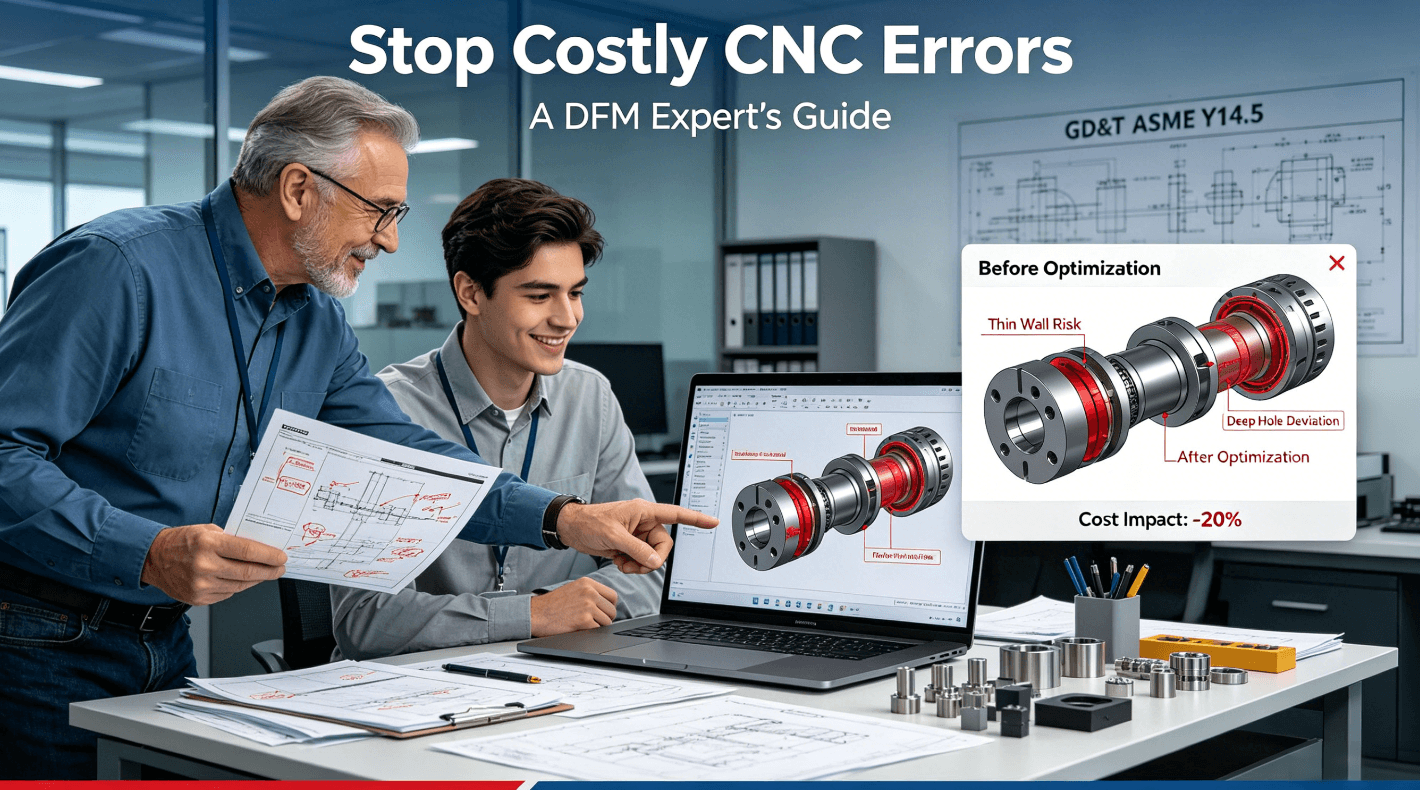
Expert DFM analysis of CNC parts goes way beyond checking the minimum wall thickness and/or hole diameter. It’s a pro-active analysis process that involves engineering insight into the manufacturing process mechanics. For instance, it helps one to understand how the manufacturing process will be affected by having a high aspect ratio deep bore that will cause tool deflection and tolerance loss; it predicts whether an irregularly shaped part in the fixture will cause tolerance problems; and it determines how different materials behave under cutting conditions and heating.
Basic DFM drawing check analysis is a passive exercise based on compliance with the set design rules. Expert analysis, however, involves active simulation of the process to determine its parameters like stress distribution while machining or collision between workpiece and tool. Special software may be used to visualize toolpath for more complex geometry, which cannot be detected in a static drawing review.
The basis of effective DFM needs accurate communication. This starts from applying the standardized concepts of geometric dimensioning and tolerancing (GD&T) as explained in such standards as ASME Y14.5 in an absolute manner. This common language rules out any uncertainties and guarantees that the design idea is fully interpreted by the manufacturing engineers. This serves as the fundamental framework for developing other visualization tools used for analysis and communication.
The most precious part of any engineering analysis process lies in the expertise gained over the years. This is the capacity to predict that a certain inside angle may cause stress concentration, a certain material selection may result in surface imperfections, or a certain assembly procedure may be impossible as per the design. Engineering foresight enables designers to make changes before they happen.
Digital prototyping visualization is an excellent testing ground that exposes significant problems without any risks. Using 3D rendering and cross-sections allows engineers to test-fit assemblies virtually in order to prove proper clearance, proper engagement of threads, and internal channel continuity, such as fluids. Interferences resulting from cumulative tolerance stacking in assemblies are detected early on in the process.
Although 2D drawings provide information on the parts themselves, digital prototypes enable engineers to simulate an assembly of all parts together. Animation of assembly allows to detect whether there is sufficient room for tools, whether fasteners will engage properly, and whether there are interferences between parts. It is particularly important when assembling housing or mechanisms comprised of multiple parts where just one incorrect fit may bring production to a standstill.
The photorealistic rendering of an industrial design is one of the most powerful tools that can be used to communicate with non-engineering stakeholders. It makes a complicated technical drawing into something that can be easily understood by anyone. This capability is very important for obtaining approval for design modifications, informing managers about any possible risks, and bringing various teams together. If a change is presented through a “before” and “after” rendering, its value will be immediately obvious.
Collaborating with a CNC turning services company that has the ability to use these digital models for collaborative analysis provides a means to link design and manufacturing. It gives the opportunity for manufacturing experts to examine the digital prototype, evaluate the manufacturability of the design, and give input in terms of fixture and tool designs and the ideal orientations of the part during the machining process.
Material selection is crucial to cost, performance, and machining ability. Visualization takes such decisions past data sheets. Microscopic images can be used to show the microstructures of various metal alloys, thus helping engineers make predictions about the finish after the machining process. The use of charts can visually show how hard the alloy is compared to tool wear or how high thermal conductivity relates to the possibility of part distortion – a visualization process that prevents sourcing mistakes.
Graphics in technical specifications and Imaging for quality control can be highly effective in the supplier screening process. Do not take what is written at face value; ask for pictures – close-up macro photography of the supplier’s manufacturing of similar components, videos showing the supplier’s process control systems, as well as imaging from inspection reports. Pictures can tell much more about a potential supplier than a typical capabilities brochure.
In qualifying CNC turning part manufacturing suppliers, ask for pictures of the initial product inspection documents with measurements of important dimensions taken using a CMM. Ask for high-resolution pictures of surface finish details or certain features such as thread or groove details. These manufacturing process control documents serve as a clear insight into their level of precision and accuracy.
ISO 9001, IATF 16949, and AS9100D certifications require documented procedures and objective evidence of conformance. One could see by themselves whether the supplier is following the above criteria. For example, does the company have calibration gauges illustrated in its documentation? Is there any photographic evidence of the set-up and the results in their inspections? Visual traceability is an indicator of the maturity level of the supplier’s quality culture and process management.
Use technical images for clear communication regarding the quality standards. During procurement process, one should share with potential suppliers images with key annotations highlighting critical to quality features, examples of surface finishes, and inspection points. Such approach will help to ensure alignment of understanding from the very beginning of discussions to prevent misunderstandings in the future. The process of receiving a quote will become much more straightforward.
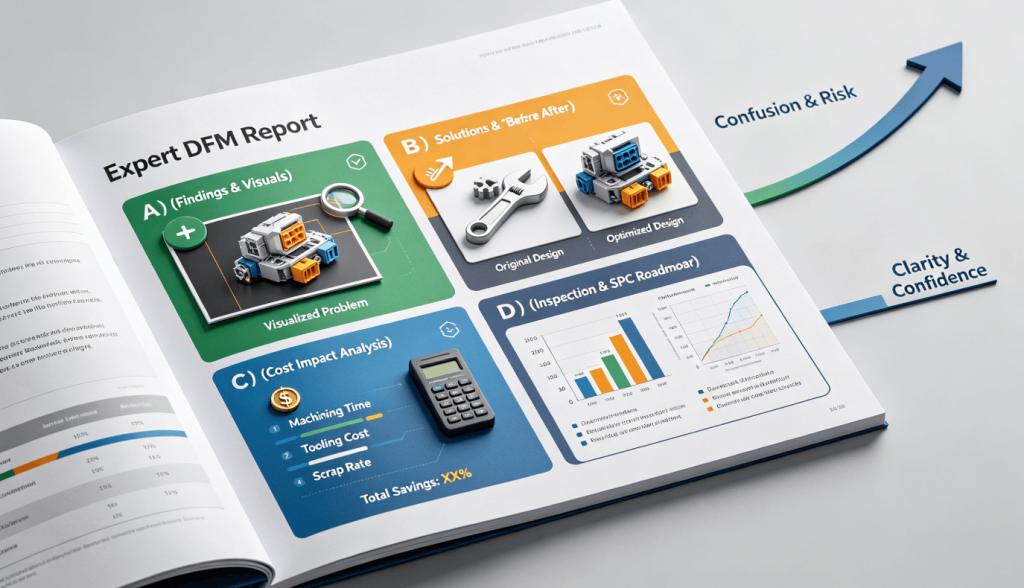
An expert-level DFM report is a tool that helps make decisions and is more than a problem checklist. The report needs to include: 1) Prioritized plan of actions, 2) Visualized solutions to different scenarios (“before” and “after”), 3) Cost impact analysis of various designs, and 4) Inspection methods recommended for implementation. With such a report, a negotiation session will be shifted from a discussion only about the unit price to talks about TCO and risks reduction.
The best defense against such mistakes would be to institutionalize this process. Your organization needs to create its own standardized checklist for visual DFM. With this living document, you can turn your expert analysis into a consistent organizational resource rather than an on-demand service, which will help you save time and effort while preventing any similar mistakes from happening again in the future.
Your checklist should cover all critical domains, such as geometry and tolerances (example drawings of correct and incorrect practices provided), material and finish selection (sample pictures and material properties table included), assembly and testing (assembly diagrams required), and supplier qualification (scoring matrix to evaluate the technical imaging submission).
Every criterion in the checklist must contain numerous visuals. For example, under the “Surface Finish,” it is necessary to provide photos illustrating the difference between “Ra 0.8µm” and “Ra 3.2µm.” For the “Edge Quality” requirement, an acceptable deburred edge vs. an unacceptable sharp edge must be illustrated. All technical specification graphics will serve as an objective standard that removes ambiguity and guarantees that all designers and engineers perceive the same requirements.
This checklist should not be where the list is static but that is always changing, then every project’s learning outcomes that it adds to the team. Whenever an activity is learning to be identified, the visual and the solution should be listed in the checklist. This will then foster the team to constantly have new additions, added to and expand with more engineering content creation, which will become part of the knowledge management system.
With precision CNC turning, the most cost-efficient enhancements will happen even before the first part is turned. With the combination of thorough DFM analysis expertise and advanced technical visualization tools, engineers will move their focus from solving problems to preventing them, shifting the line of defense up the chain. Not only do they make sure that there will be no mistakes, but they are making this an inherent feature of their job that allows them to develop innovative solutions, ensure on-time delivery, and maximize return on investment.
Q1: When should we involve a supplier in DFM analysis?
A: It’s recommended to involve suppliers as late as possible, after detail design but before the part was built. the earlier they are involved, the simpler it would be to change design. I believe it is already too late to involve them at the prototype stage, as all the changes would be too time and cost consuming.
Q2. What part of the design is most costly when errors in CNC turning are considered?
A: These are excess specification of tight tolerances which require extra processing, thin walls causing vibration, lack of clearance for tool access and material selection which is not machinable or does not perform well in the application.
Q3: What should be done in order to objectively compare bids from multiple suppliers which differ significantly?
A: Your DFM analysis will serve as an objective measure. A much lower bid could mean hidden problems in manufacturability. Ask for a process flow and proof of capability for key features in the design. The comparison should focus on the overall value and risk mitigation of the solution, rather than the unit price.
Q4: Is DFM analysis required only for difficult parts?
A: No, even a basic part could have hidden mistakes. A simple spacer with incorrect parallelism may result in improper assembly, a shaft with an inappropriate groove will surely fail. DFM for a simple part will help to ensure its durability, choose the best possible manufacturing process, and avoid the expensive mistake of producing faulty designs at scale.
Q5: What are the results expected after DFM analysis?
A: The results would include a complete report that contains the following items: list of manufacturability problems with appropriate pictures, recommendations on how to adjust the design, assessment of material/process options, along with their advantages and disadvantages, and suggestions on critical inspection procedures.
This article is derived from the expertise of an expert in precision manufacturing and design for manufacturability with more than 15 years of industry experience, specifically in turning challenging designs into cost-effective manufacturing processes. For a risk-free manufacturing experience, LS Manufacturing is offering free expert analysis services in design for manufacturability. Upload your drawing now and receive a professional risk assessment.